Sinclair ZX81 modification, preventive maintenance and common fixes
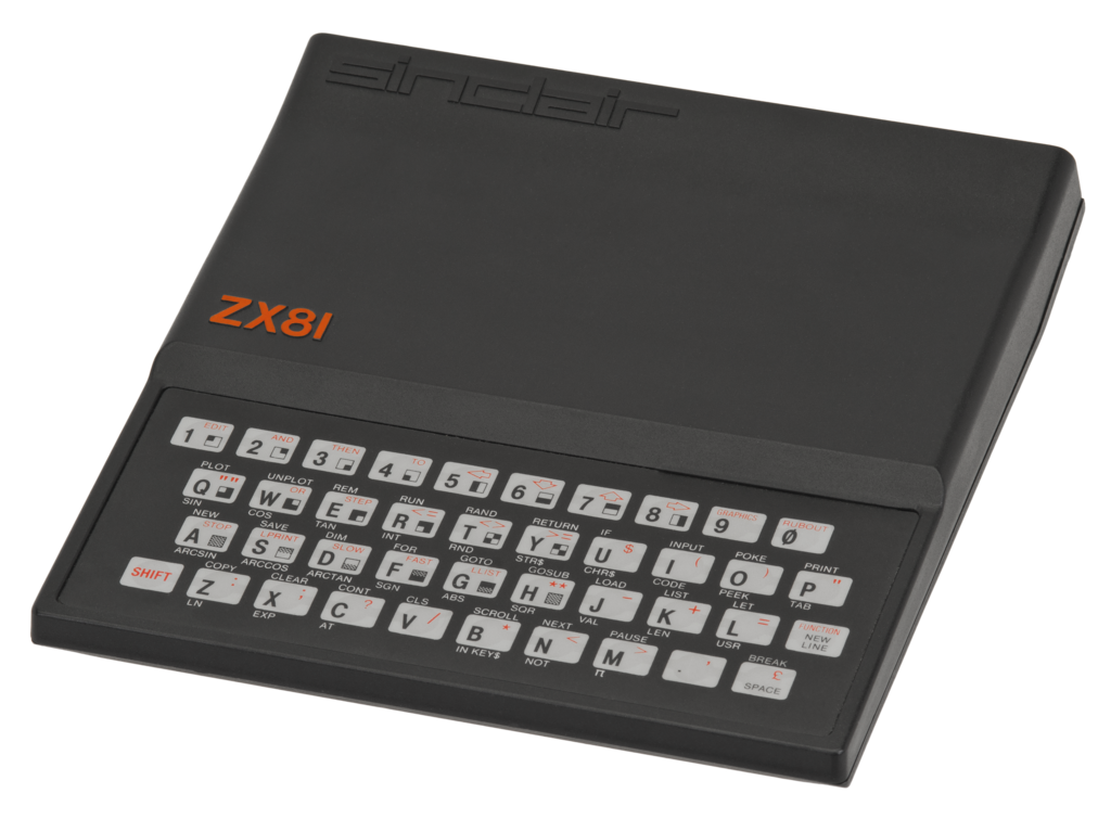 So, I got myself a Sinclair ZX81 from the UK. I got lucky and found one that came boxed, complete with 9V power supply, assembly instructions and 16 KiB RAM pack. The ZX81 was Sinclair’s 1981 follow up of the ZX80 computer (1980) and was sold as a kit or fully assembled. Like it’s predecessor it sported a Zilog Z80 CPU running at 3.25 MHz and 1 KiB of RAM. It’s main advantage was the lower cost and larger ROM (8 instead of 1 KiB) which allowed for more BASIC commands and floating point math support.
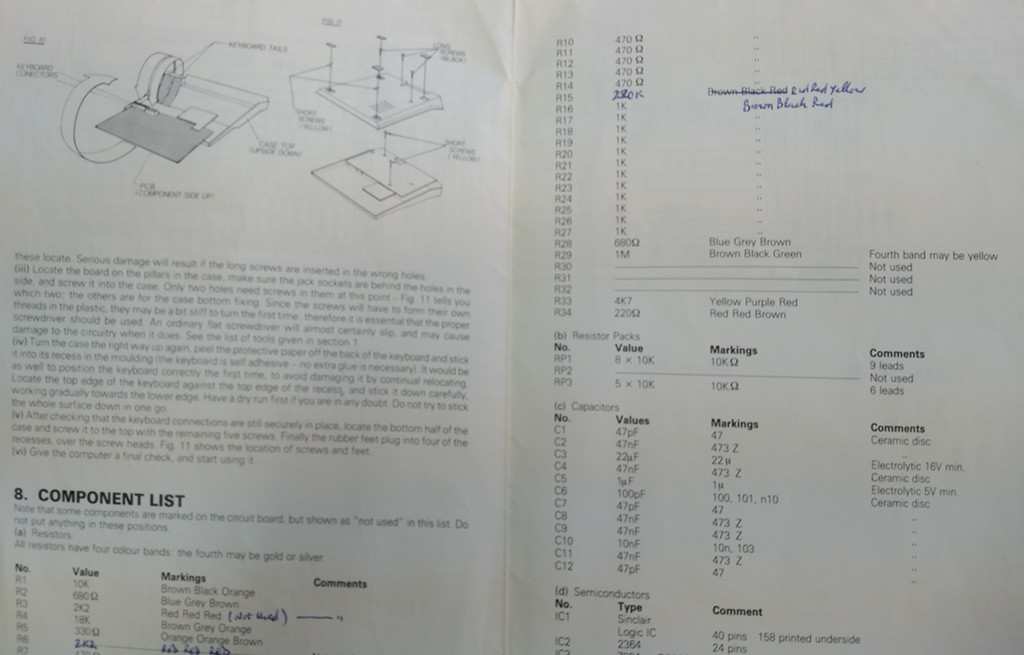
My unit was of the kit version and the original owner did a very good job of cleanly soldering it together and they even noted some errata in the assembly instructions, where a resistor had to be replaced with a different type – the schematic on the back side of the instructions did show the correct value.
Given the age of the computer, I did expect to find issues with it, but in the end I mostly performed preventive maintenance and a modification to allow the use of the ZX81 with a modern screen with composite input. Only one of the keyboard ribbon cables had a crack at right at the plug, a rather common failure. Thankfully, due the popularity of the ZX81 in the UK at the time, there is still a very active community of ZX81 users around and I could find many helpful guides, which I will link to, below.
Power Supply
A British computer from the early 80s obviously comes with a BS 1363 plug and expects 240 Volts AC as input. Here in Switzerland we use type J plugs and around 1987 mains voltages across Europe were standardized to 230 Volts – in Switzerland it used to be 220 Volts. In any case, the mains plug was quick to replace. The voltage of 230 Volts is still in spec for the old power supply. Next I checked the output voltage and measured a bit above 10 Volts, which is within spec when no load is attached.
The ZX81 has no power button, you simply turn it on by plugging in the power plug. Make sure you plug it in the right plug – it is the one most forward and clearly labelled on the case, but Mic and Ear are right next to it and they all use the same 3.5mm audio jacks.
Heat Sinks
Upon power up I could confirm that the original voltage regulator properly reduced the 9V down to 5. I did notice that the Ferranti uncommitted logic array (ULA) chip, which produces the video signal, and the Zilog Z80 CPU, got pretty warm to the touch, but not as burning hot as the voltage regulator, which is screwed on a large aluminium heat sink plate. The latter being hot comes as no surprise, since it has to drop the 9 Volts down to 5, effectively turning 4 Volts into heat. Since the mechanical stress due to heat up and cool down is a large reason for the ageing of integrated circuits, I did add heat sinks to the ULA and CPU. Later I also replaced the voltage regulator with a cooler running solution (see below). All of this is intended to reduce the heat stress from turning the computer on and off on these chips, especially in such a tight case with minimal air flow and no active cooling. This should increase their lifetime.
Video Output
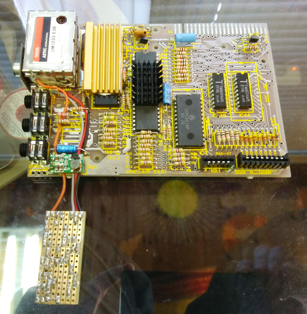
Since modern screens with RF input are now difficult to find, especially since the switch from analog to digital TV signals, I would argue that a composite video output is an acceptable compromise. In case of the ZX81 it is possible to get such an output without damaging the case and with reversible changes to the electronics. Only the RF modulator’s video input and 5 Volt supply need to be detached. The RF modulators‘ RCA jack can be reused with a composite video cable. It is already attached to ground, only it’s center pin needs to be re-soldered to a new video signal.
 The Ferranti ULA chip’s pin 16, labelled UK2 next to the RF modulator, delivers a PAL composite signal. For the later revisions of the chip, it’s signal can be boosted with an NPN transistor and a current limiting, small resistor. This circuit is described in a few variations on a number of sites. Since this modification is simple to do, I recommend you try this first – it may be all that is required to get your ZX81 to output a composite signal.
In my case the ULA is an earlier revision, which doesn’t output a back porch signal. This has the effect that the screen fails to synchronize with the video signal and the picture moves rapidly from bottom to top on the display. Ziggurat Communications Ltd. published a great video explaining what a back porch signal is, how it can be generated and provides a solution to fix this (mirror), using just a strip board and either discrete components or a 555 timer chip.
I highly recommend to go with the 555 timer based circuit, if you do have one handy. This not only requires less parts to solder down, it also makes for a smaller foot print of the circuit board. It should fit neatly into the RF modulator case, if you remove the small circuit board that is inside. This would make for a very neat modification, preserving the original look of the board.
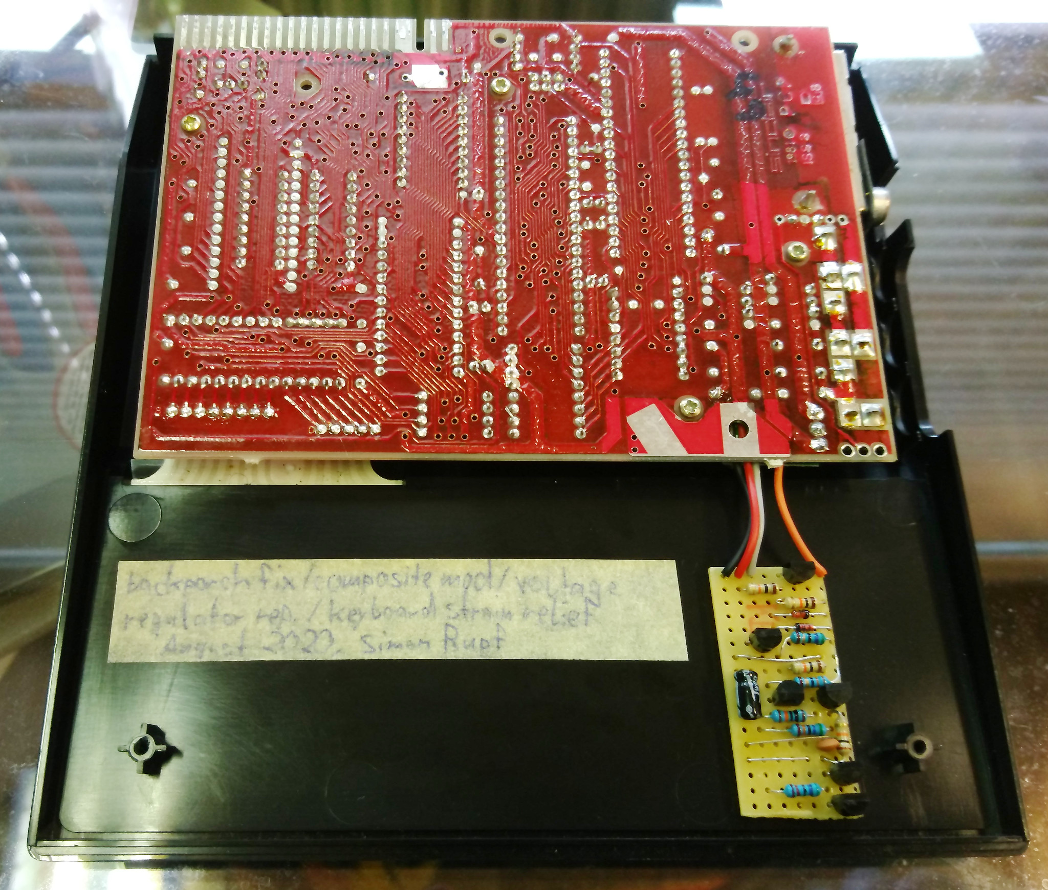
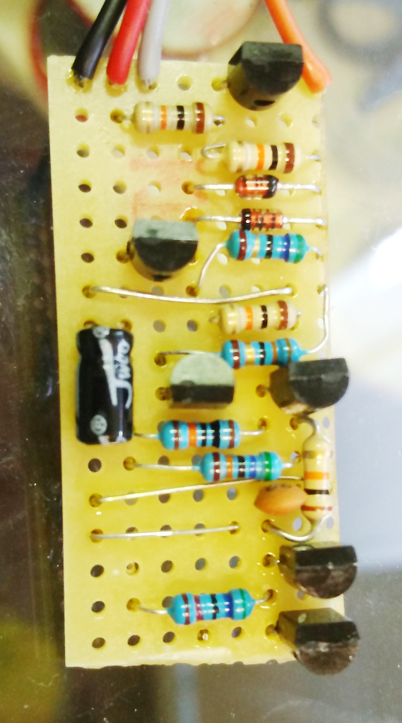 While I could have sourced a 555 timer from another project, I didn’t want to bother de-soldering it or wait for new stock to arrive when ordering from China or pay the ten fold prices at a local hobby electronics store. So I implemented the version using discrete components, which form an astable multivibrator circuit to generate the back porch clock signal. This lead to a larger strip board, which doesn’t fit in the RF modulator’s metal can, hence it dangles next to the board – I did attach it with some foam pad to the case. Also, because there are more components involved, this is more error prone and I did make several mistakes putting it together. I accidentally bridged a cut in a strip and missed connecting one of the ground rails. If such a self implemented circuit doesn’t work, it requires patience to go through the schematic, compare it with the board and test continuity on the expected points and non-continuity on others, until the mistakes are all isolated. I really am spoiled by todays readily available, cheap printed circuit boards, that avoid many of these pitfalls.
In any case, if you happen to be a cheap skate and/or impatient like me, here are the Fritzing drawings and bill of materials for the discrete component version of Ziggurat Communications Ltd.’s back porch fix, once a populated drawing and one to highlight where the strips have to be cut:


Voltage Regulator
As mentioned above, the voltage regulator needlessly burns a lot of power to get those 9 Volts down to 5. It is the primary source of heat related stress in the small case. While more efficient circuits existed even at the time the ZX81 was made, still a lot of electronic products use the LM7805 voltage regulator, because it is so cheap and requires only two additional capacitors to work. These days we have handy and relatively cheap (less then a buck, but not pennies like the 7805) drop-in replacements in the form of small buck converter boards or switching regulators. I used a DD4012SA buck converter module that I had around and it seems to do a decent job. Another good choice are the R-785.0-0.5 switching regulators. Both will fit right in place of the LM7805 and have the same pin-out as it.
Keyboard Connectors
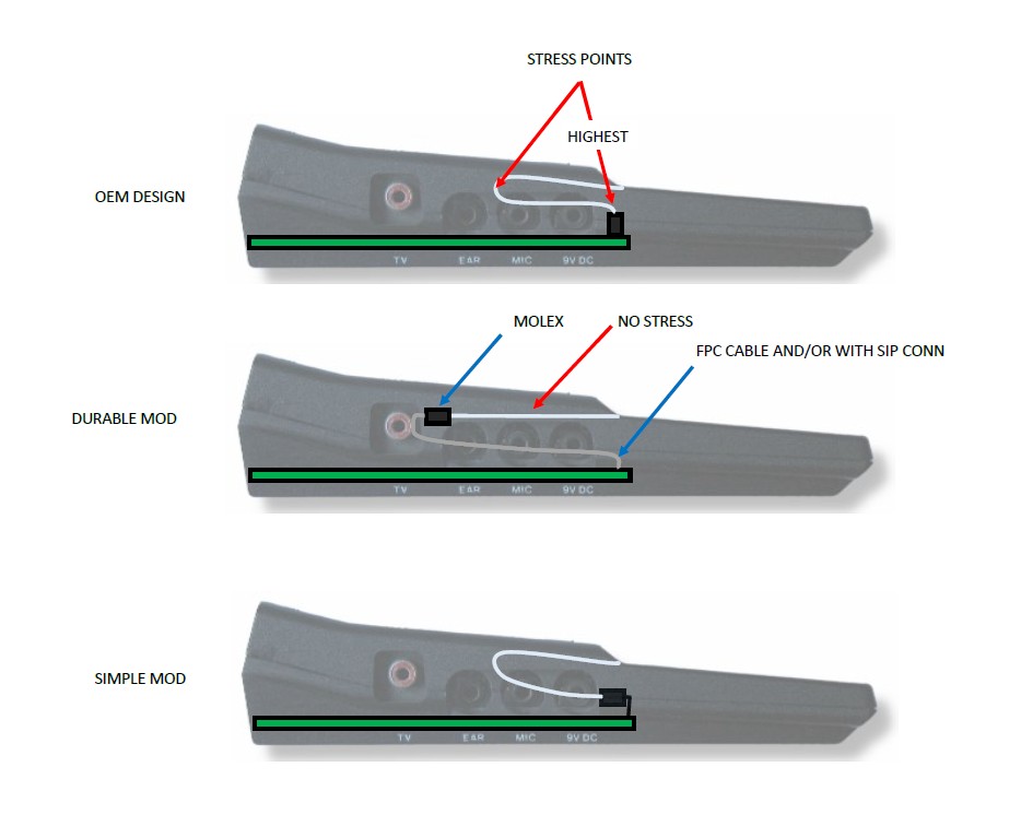 Turning my attention to the keyboard I was not surprised to find that none of key presses registered. While the pressure sensitive membrane keys are a chore to type on by themselves, the real problem with these keyboards are the thin plastic strips that hold the conductive traces – they get brittle with age and crack where they are under mechanical stress. User Gamma Ray explained it best on the Sinclair ZX world forums with the diagram, here on the right.
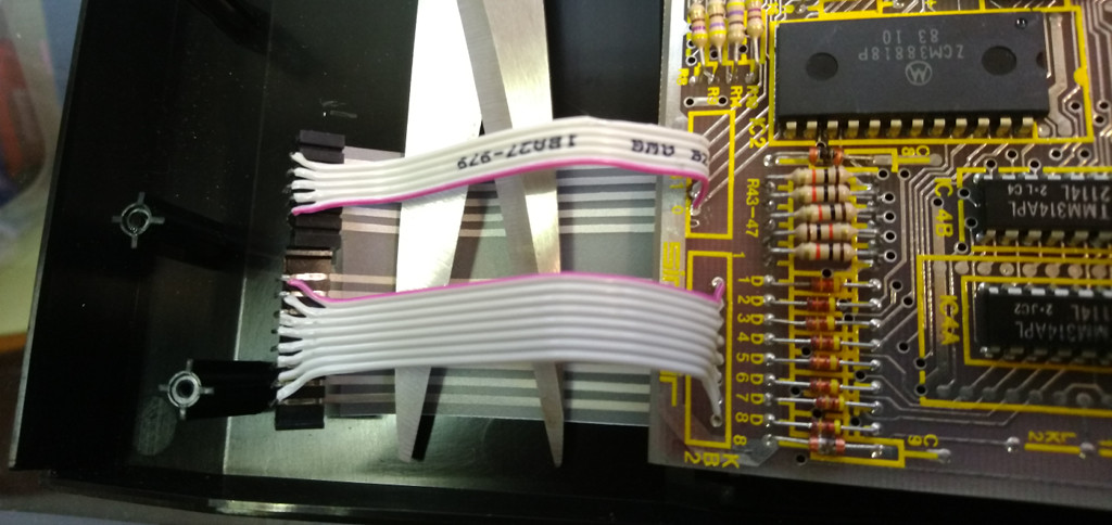
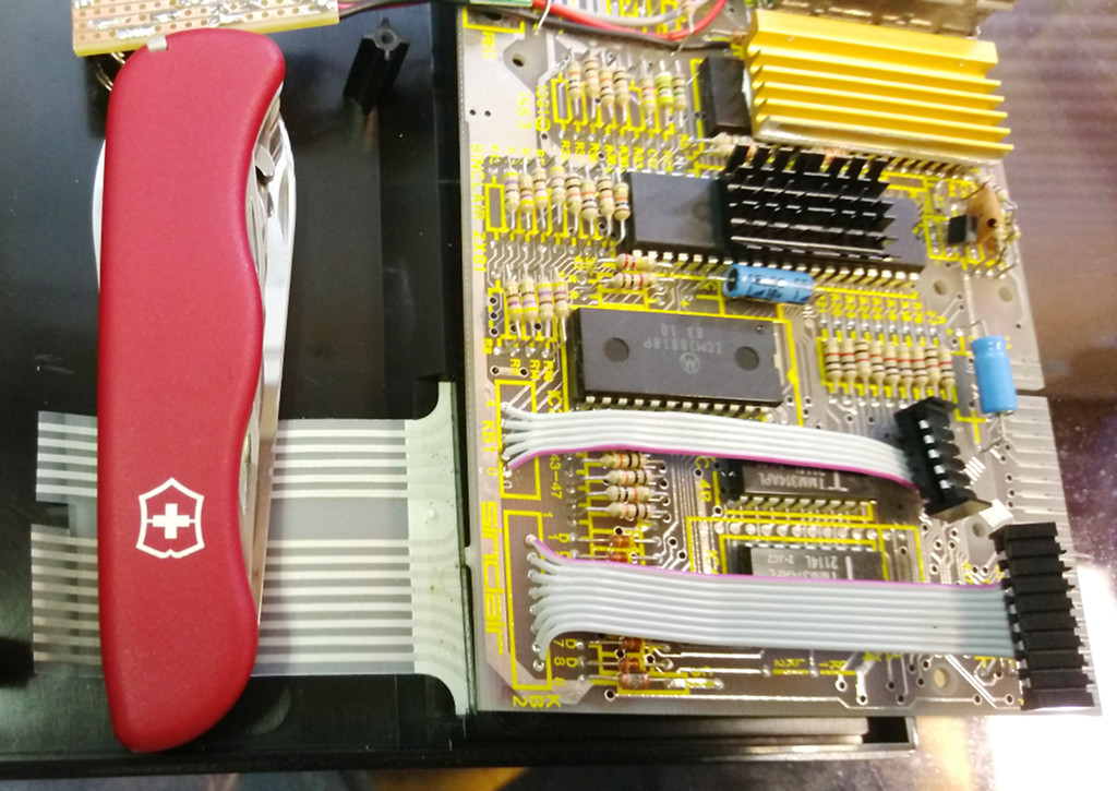
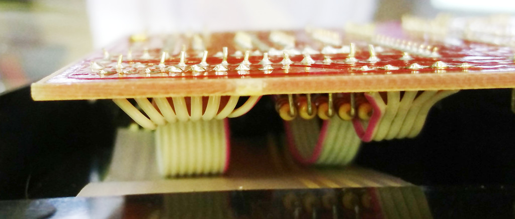
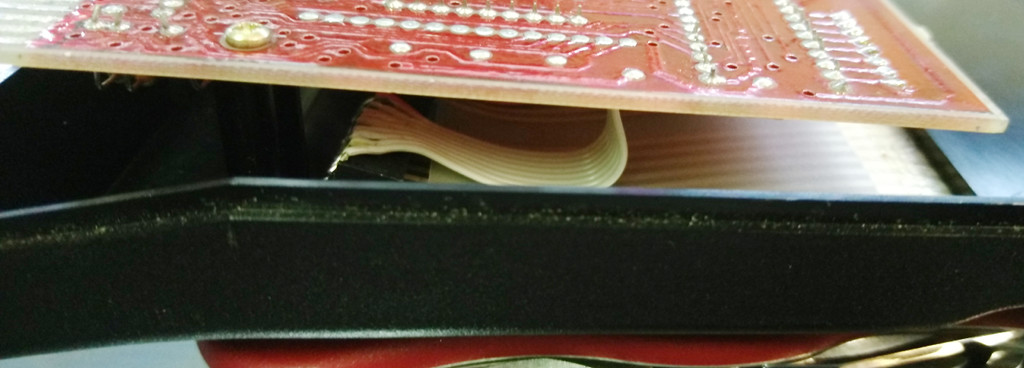
Indeed, my unit had a crack in one of the two ribbons, right at the edge where it was plugged in to the connector. This meant that my ribbons were still pretty long and the bad part could be cut off and it would still reach the plugs. But in order to get a more durable solution, I de-soldered the connectors and attached two flexible ribbon cables to the board, to avoid any such stress on the original cables in the future. They were sourced from an old serial connector extension cable – a 40 pin IDE or floppy disk cable might do just as well. I recommend checking for continuity from keyboard ribbon trace to the ZX81 mainboard for every single pin, to detect misaligned plugs or bad solder joints, before you turn on the device.
Conclusion
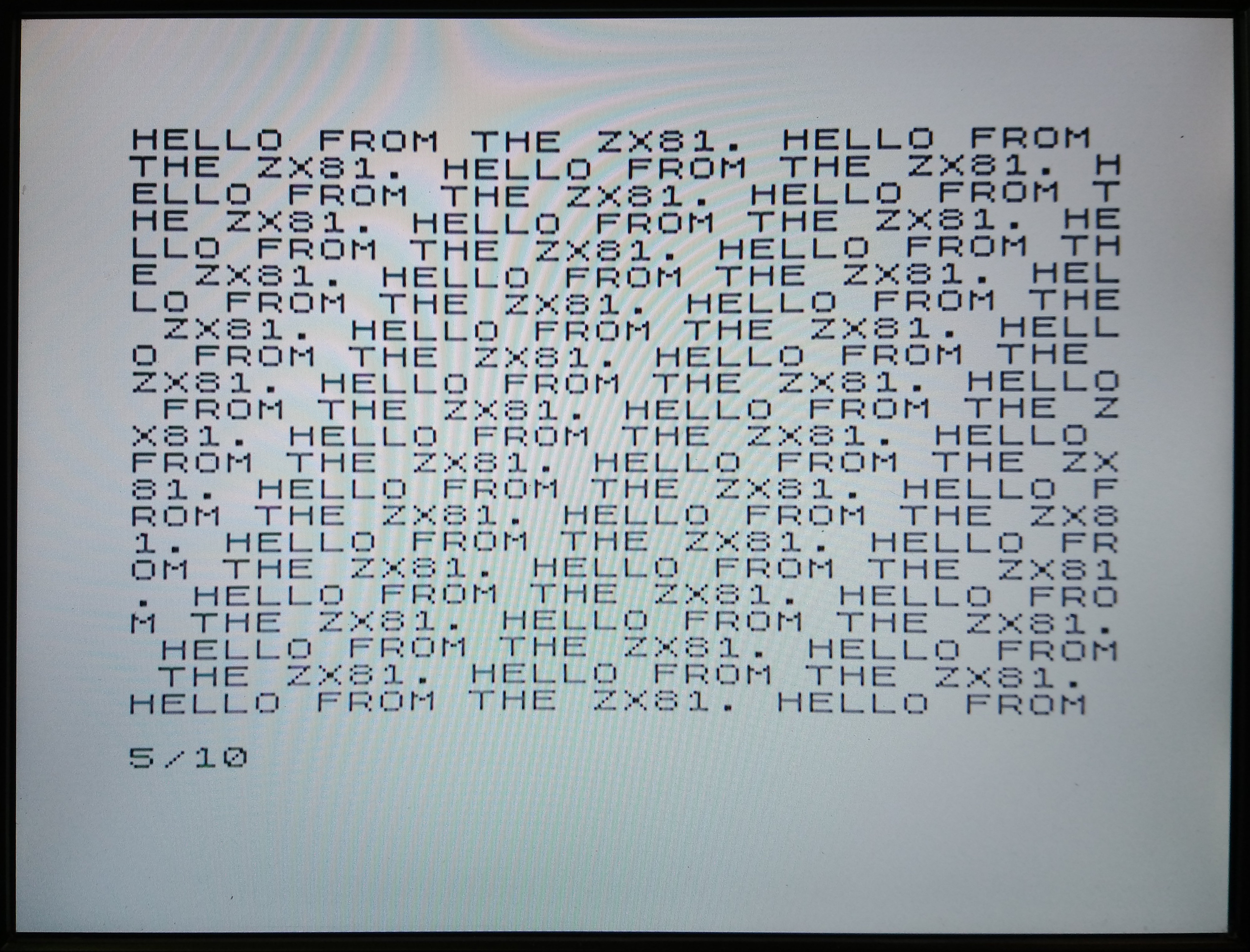
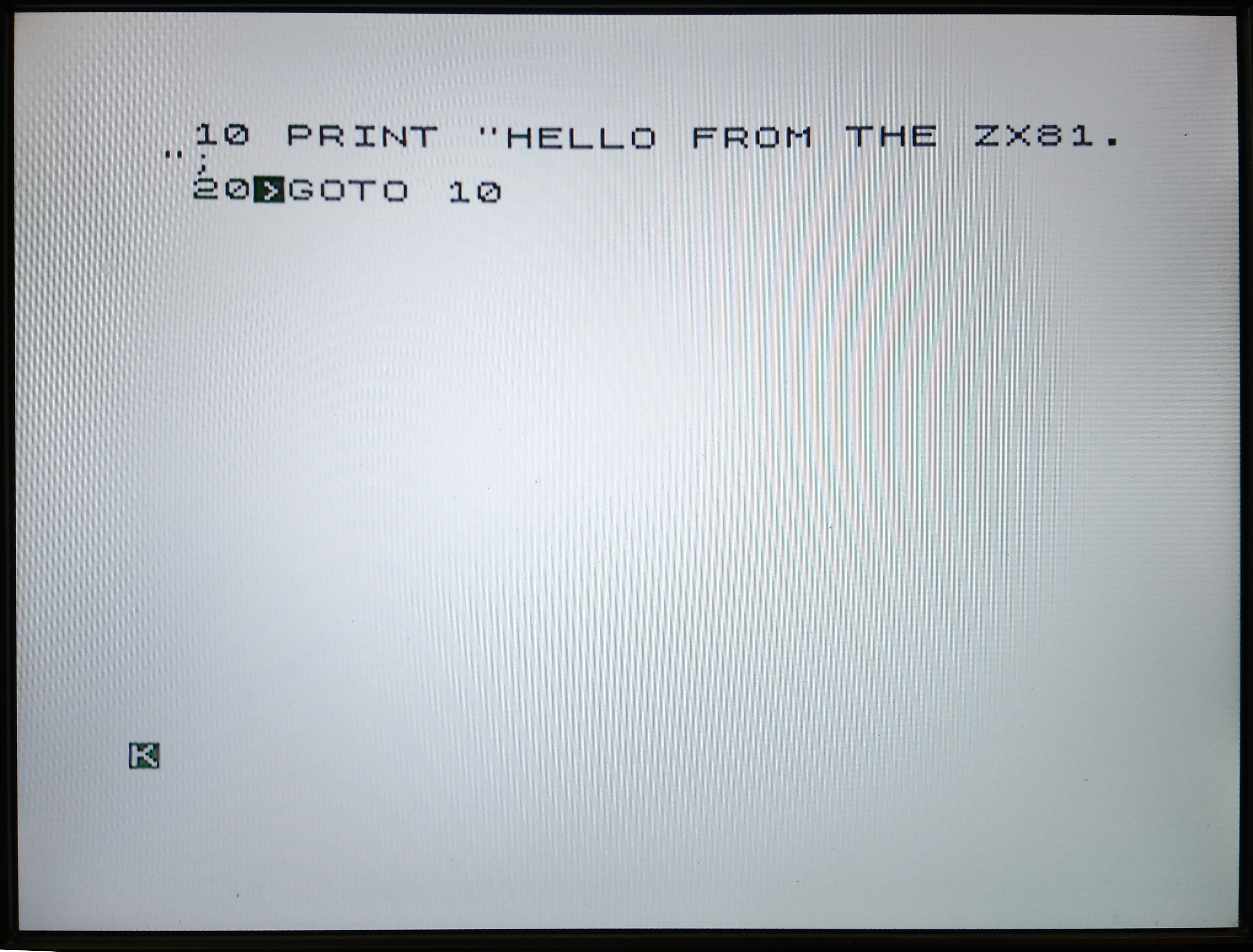
After all this work, I have a ZX81 that plays nice with modern screens and has a working keyboard. The video signal is clear and has a good contrast. I managed to type in the obligatory „Hello world“ listing in BASIC. The command keys to speed up entering programs are a nice touch, given that the keys presses do not offer a tactile feedback. Still, I prefer even a ZX Spectrums „dead flesh“ keys any day over the ZX81’s touch membrane. Hope that with the preventive maintenance, it lasts another 40 years.
Discussion Area - Leave a Comment